
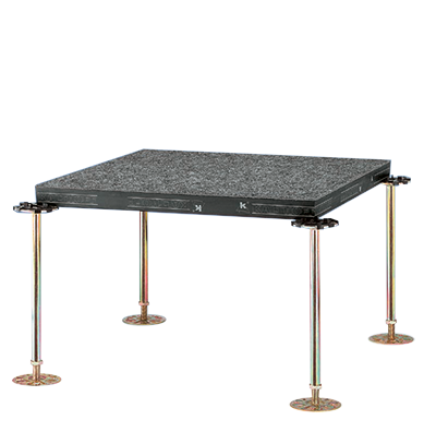
SYSTEM K 1060 PB
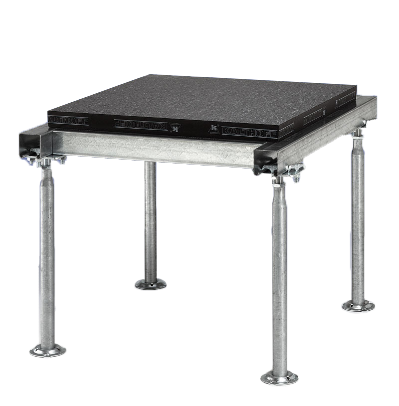
Raised floor comprising height-adjustable tubular steel pedestals, C-profile stringers, floor panels and surface coatings.
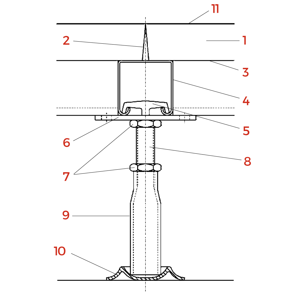
| 1 | Multi-layered, high-density chipboard or mineral fibre panels |
| 2 | Plastic edge trim, 0.6 mm thick, conductive/insulating |
| 3 | Thin sheet aluminium or steel, mineral fibre panels, also available without underside coating |
| 4 | C-profile, 60 x 60 x 2 mm |
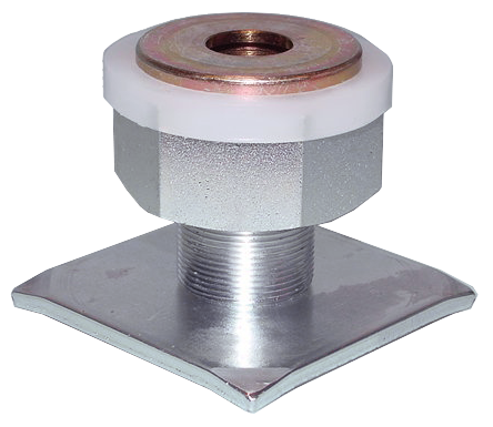
| 5 | Hammer-head screw, M 10 |
| 6 | Steel gasket, 110 x 110 x 5 mm |
| 7 | Flat nut, M 20 |
| 8 | Threaded bolts |
| 9 | Column, 1’’ (DIN 2440) |
| 10 | Steel pedestal base |
| 11 | Your choice of floor covering: e.g. PVC, linoleum, rubber, textile |
APPLICATION
To create cavities for the installation of all types of cables, primarily in instrument and control rooms, high and low voltage systems, control rooms, transformer rooms, etc.
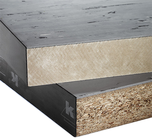
FLOOR PANELS
The multi-layered, high-density chipboard or mineral fibre floor panels are stencil milled in our factory to fit seamlessly together. The cut edges of the floor panels are protected by plastic trim (except for panels cut on site). The floor panels are manufactured to satisfy the respective load-bearing requirements. Depending on the area of application, the undersides of the floor panels are lined with aluminium sheet or galvanised sheet steel. All commercially available floor coverings made of PVC, linoleum, rubber or textiles suitable for raised floor applications can be used as floor coverings. A wide range of colours and patterns is available.
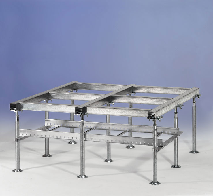
SUBSTRUCTURE
The floor panels are installed on a substructure of galvanised, tubular steel pedestals which are anchored to the subfloor. Screws are used to attach the C-profiles to the supporting pedestals and the gaskets. These screw fastenings are electrically conductive in accordance with the provisions of VDE. The floor’s grid size is tailored to the customer’s specified load-bearing capacity and can be infinitely height-adjusted thanks to the pedestals’ adjustable threads. For inspection or retrofitting, the floor panels and the grid system can be completely or partially dismantled.
TECHNICAL DATA
| Substructure grid | 1.200 x 600 mm / 600 x 600 mm |
| Floor panel grid | 600 x 600 / custom specifications upon request |
| Floor panel thickness | approx. 40 mm |
| Distributed load-bearing capacity | 15 – 30 kN/m² (substructure grid 600 x 600 mm) |
| Point load | 3 kN / 5 kN |
| Height | 180 – 2.500 mm |
| Supporting structure | Height-adjustable steel construction ±30 mm |
| Weight | Depending on the selected substructure and floor panels, approx. 40 – 80 kg /m² |
| Fire protection specifications | F30, B2, B1, A2 |


FOR ADDITIONAL TECHNCAL INFORMATION AND ADVICE ON ALL OF OUR SYSTEMS AND PRODUCTS,
CONTACT US TODAY
CONTACT US TODAY